X 0 1 2 3 4 5 6 7 8

Section One
N-1 Body Problem
1. Small Ellipses
X 0 1 2 3 4 5 6 7 8 |
|
Section One |
| N-1 Body Problem |
| ___ |
| 1. Small Ellipses |
| 2. Symmetric Plane |
| 3. System Wave |
| 4. Binary 4BP |
| 5. Barycenter |
| 6. Interference |
( 27 ), or an envelope surface in the non rotating system.TAB 3 THE SYSTEM WAVEABSTRACT
The motion of the planets is transformed into a new coordinate system, i.e. with respect to the invariant plane and a model is constructed to explain the behavior of the planets, collectively. The result is a physical graph of two distinct wave patterns, with the Earth (or moon, depending on the orientation) at the "g-spot." One pattern applies to the inner planets, the other to the outer planets. This model fits several aspects of the planets: inclination of axis of rotation, ellipticity of orbit, and inclination of the orbit. These parameters are not explained by any other theory. The solution is an envelope curve
A Geometric Study
The first objective of the analysis is to create a more stable system by better explaining systematic deviations from the symmetric plane. In order to further define the motions, first introduce another variable: the planet’s axis of rotation. This axis is known to always point to the same spot in the celestial sphere, throughout its revolution around the sun. During this movement, the planet moves evenly above and below the ecliptic plane. These characteristics can be conveniently represented if the planet is considered to be associated with a longitudinal wave. If the axis of rotation is always tied to this sinusoidal wave, then as the planet moves about the sun the elliptical shape of the orbit causes the planet to move closer and farther away from the sun. If this motion happens on a sinusoidal wave, the axis will always point in the same direction.
Otherwise, the choice of a sinusoidal waveform explains the three movements that occur simultaneously with respect to the new system plane: the elliptical shape of the orbit, the movement above and below the system plane, and the axial inclination of the planets pointing to a fixed spot in the heliocentric sphere while the other motions occur.
The data used in the analysis is listed in Table 1. The semimajor axis is an approximation of the planets’ average orbital distance from the sun. A value "X" is the range of motion of the planet in its orbital plane.
|
Planet |
X |
Axial inclination |
Semi major axis |
|
Mercury |
5.8 E7 |
0.0 degrees |
1.2 E7 km |
|
Venus |
1.1 E8 |
R179 |
6.7 E6 |
|
Earth |
1.5 E8 |
23.5 |
2.5 E6 |
|
Mars |
2.3 E8 |
25.2 |
2.1 E7 |
|
Jupiter |
7.8 E8 |
3.2 |
3.8 E7 |
|
Saturn |
1.4 E9 |
26.8 |
7.8 E7 |
|
Uranus |
2.9 E9 |
R98 |
13.2 E7 |
|
Neptune |
4.5 E9 |
29.0 |
3.7 E7 |
|
Pluto |
5.9 E9 |
90.0 |
1.5 E9 |
Table 1
The next task is to find the wavelength of a common "system wave." After trying several solutions, it was evident that the outer planets would be the controlling elements, so the search focused on the lowest common denominator of their orbital range. This value, 23.3 E6 km also had to fit the entire range of movement of the inter planets.
The second column of Table 2 lists the aspect of each planet upon this wave – the remainder of division by the proposed wavelength. This value was used to situate each planet at the proper location upon the wave. Note that positions are only approximate in this two dimensional system: the wave is actually a spiral or helix in three dimensions.
A possible presentation of the "system wave" is a family of curves called the Cochoids of Nichomedes, with the parametric equations:
x = a + cos t AND y = a tan t + sin t
These generate a two-part curve: a loop similar to a prolate cycloid, and a shell. This solution will have some unique possibilities in the analysis of orbits.
The second objective of the analysis was to further develop the study to define the uniform deviations from the new system plane, so that a more stable system could be devised. This has been done for the original positions by simply introducing another variable and trying to match it. By seeking a close fit to this third variable, axial inclination, the affect was to more closely resolve the previously analyzed parameters. This affect becomes more pronounced as the analysis continues in greater detail.
|
Planet |
Division by 23.3 E6 |
Inclination of orbit to the ecliptic |
Maximum distance from the ecliptic |
|
Mercury |
2 + 1.1 E7 km |
7.0 deg |
7.0 E6 km |
|
Venus |
4 + 1.7 E7 |
3.4 |
6.5 E6 |
|
Earth |
6 + 1.0 E7 |
0.0 |
- - |
|
Mars |
9 + 2.0 E7 |
1.9 |
7.6 E6 |
|
Apollo Group |
9 + 7.8 E6 |
- |
- |
|
Belt Asteroids |
16 + 2.2 E6 |
- |
- |
|
Trojan Group |
33 + 3.6 E6 |
- |
- |
|
Jupiter |
33 + 1.1 E6 |
1.3 |
17.0 E6 |
|
Saturn |
60 + 2.0 E6 |
2.5 |
61.0 E6 |
|
Uranus |
124 + 1.0 E7 |
0.7 |
35.0 E6 |
|
Neptune |
193 + 3.1 E6 |
1.8 |
141 E6 |
|
Pluto |
253 + 5.1 E6 |
17 |
172 E6 |
Table 2
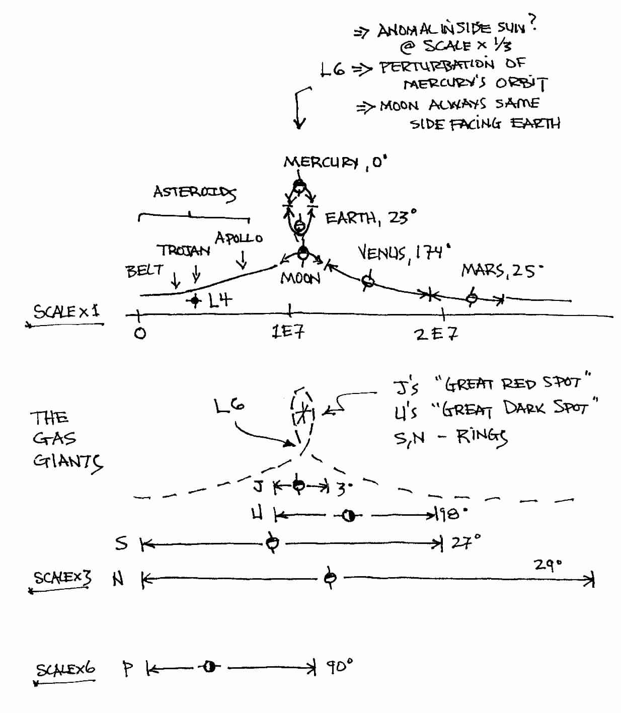
Later is a sketch of the planets situated upon either of the two parts of the cycloid, according to the average orbital distances in Table 1. The axis is shown as an arrow pointing according to the right hand rule for the planets’ rotation. The positions of the various planets on the waveforms can now be fit to the wave.
First, the motion of Mars moves uniformly on either side of an inflection point in the wave, its axis inclined at about the right amount. Jupiter does the same thing on the lower wave, which arches less to correspond with the lesser axial inclination of Jupiter’s axis. Uranus, also on the lower wave, moves through an entire wavelength, with an eight degree axial inclination off the vertical, slightly greater than Jupiter – since it traverses more of the wave.
Next, Saturn on the lower wave traverses two wavelengths, with a much greater axial inclination. The center point of the wave can be thought of as an inflection point, motivating the body to rotate in order to maintain rotational stability – a two dimensional vista of the singularity at the sun discussed earlier. It is interesting to note that all four planets (with the possible exception of Pluto) have almost the same rotational period – about ten hours. This would imply some similarity in the wave analogy, and it is there in the form of the inflection of the wave traveled.
The System Wave
Back to the upper waveform, there is Mercury shown atop the loop, It moves back and forth on the waveform the distance of its ellipticity, maintaining its axis pointed in the same direction. Although the planet is known to have an axial inclination of zero, the wave may be inflected so that the pattern traced is less exaggerated. The geometry of that area of the plane fits this expectation.
The Earth-Moon system is the most striking aspect of the system, buttoning up the sides of the loop. They are unique in the solar system, the Moon being the largest satellite with respect to its host in the whole solar system. This may be a necessary prerequisite for matter to exist in dynamic stability at the cusp of the wave front as shown. In which case Earth occupies the upper portion of the loop, the moon the lower, in its own orbit. The moon’s orbital plane is inclined at five degrees to the Ecliptic, as is indicated by the inflection of the lines (versus the much higher inflection of the upper cusp, indicative of Earth’s 23° axial inclination).
The close symmetry of the least squares fit to a sinusoidal slope and a sinusoidal motion of the y-intercept, and the uniform displacement of the midline of the sinusoidal motion of the planets about this plane, then a two-part pattern such as that envisioned most closely realizes both conclusions. In affect, the defining plane of motion then becomes the bottom half of the above parametric equations wave for the inner planets (see Table 3).
|
Planet |
Movement w.r.t. the system plane (Au) |
Center line |
Radius |
|
Mercury |
-0.30 + 0.21 = 0.51 |
-0.05 |
0.26 |
|
Venus |
-0.27 + 0.17 = 0.44 |
-0.05 |
0.22 |
|
Earth |
-0.19 + 0.17 = 0.26 |
-0.06 |
0.13 |
|
Mars |
-0.19 + 0.09 = 0.28 |
-0.05 |
0.14 |
|
Jupiter |
-0.10 + 0.02 = 0.12 |
-0.04 |
0.06 |
|
Saturn |
-0.30 + 0.17 = 0.47 |
-0.06 |
0.23 |
|
Uranus |
-0.77 + 0.74 = 1.51 |
-0.03 |
0.75 |
|
Neptune |
-1.21 + 1.21 = 2.42 |
0.00 |
1.21 |
|
Pluto |
-1.10 + 1.60 = 1.70 |
-0.25 |
0.85 |
Table 3
Another way to look at the "system wave" is as an envelope curve ( 27 ) or "envelope surface" made up of segments of all nine planets' orbital configurations. Thus the analysis here is more than a geometric curiosity but a common aspect of complex dynamical systems.
It is also important to note that, if nothing else, the "system wave" shows an exact correlation between orbit eccentricity and inclination or the orbit (also, perhaps, inclination of the axis of rotation) as was surmised in modeling the low eccentricity ellipse ( 2 ) , and vice-versa. Presumably perturbations to the 3BP model by other planets would cause rotation on the axis, as was suggested here.
Note that the origin of the "system wave" is at the sun, not at barycenter. That explains why the plot of t he orbits versus the symmetric plane is skewed ~ sinusoidal, and not elliptical. ( 2 )
An Electromagnetic System Wave versus the Magnetic field of a planet
Analysis
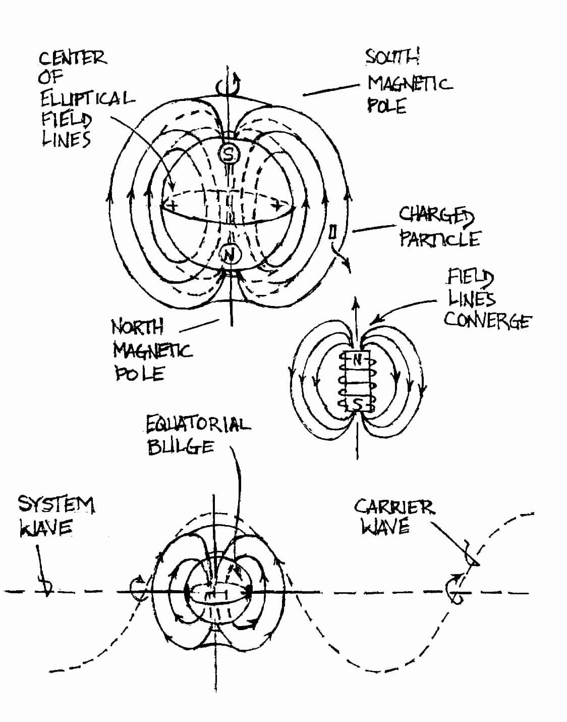
Continuing the electromagnetic analogy of ( 2 ), this helps to conceptualize the forces interacting in determining the motion of the planets - not just their orbital elements, but also the inclination of their axis of rotation. The latter comes into play because of the magnetic core of the planets. The inclusion of axial inclination adds an aspect of electromagnetism (EM) to the analysis by assuming gravity has an EM carrier wave intrinsically associated with it. ( 21 )
The illustration shows how a planet's magnetosphere might interact with an external EM force field, like a motor/generator combination. (29) Notice the ellipses of field lines are all centered at the same location, near the equatorial bulge, like a 1/r force field. A motor (generator) has a rotor and a stator. Consider the fixed, unmoving part of the device, the stator and its poles .
Electromagnetic Linkage between Planet and System Wave
The Earth, as already noted, is the stator. The rotor is formed between the symmetric and invariant planes which are both fixed - at least in the planet centered reference frame.
Notice the two planes, the symmetric and invariant planes, are the north and south poles of a single EM field, fixing the position of the planet between them. The two planes are both hinged at the same origin but the symmetric plane has an off center hinge and this makes it possible for the two planes to hold all the planets between them.
The loop in the system wave can, in this analogy, be thought of as a six pole stator.
Electromagnetic Analogy to the System Wave Loop
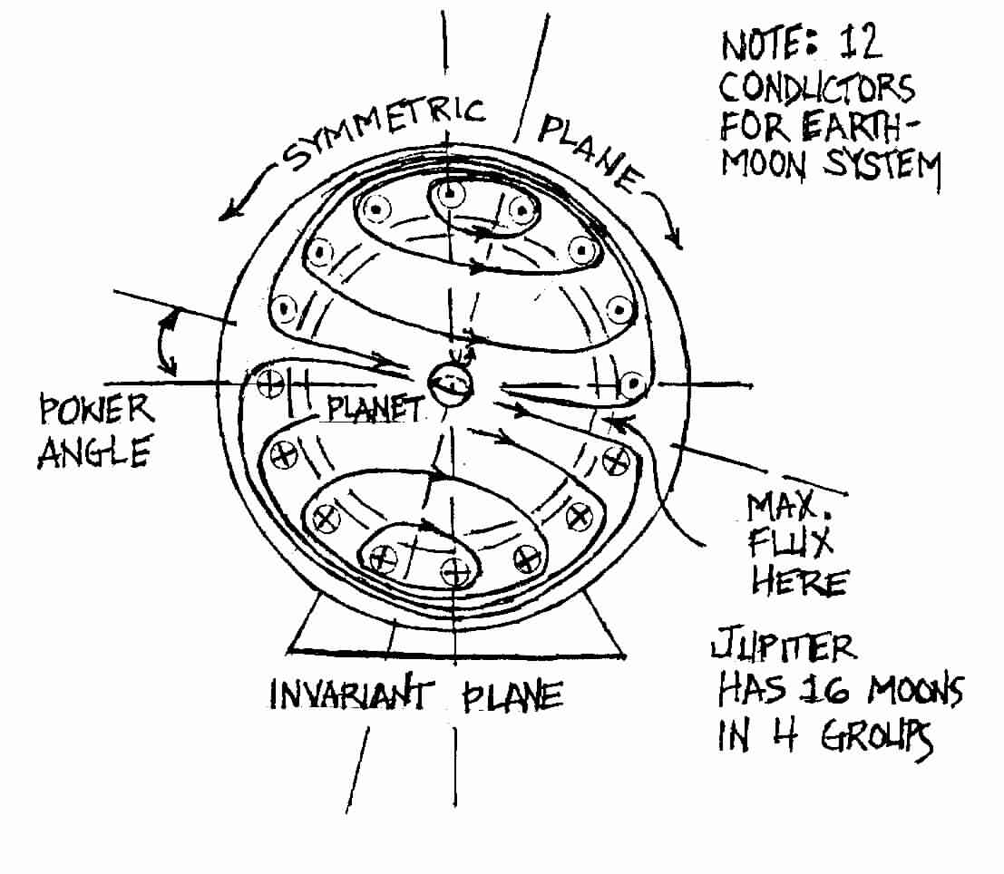
The overall action of this loop, then, is as another Lagrange Point with rotational properties of force at a distance, just as exhibited by the 1/r EM phenomena. Overall, the system acts as a three phase electrical system (3BP) with Mercury rotating to face the anomaly just like the Earth's moon rotates to always show the same face to Earth.
The outer planets have a different composition than the inner planets. They are large gas giants, versus the solid matter inner planets. So it is logical to present loops in the outer planets as less intense, more like a four pole stator.
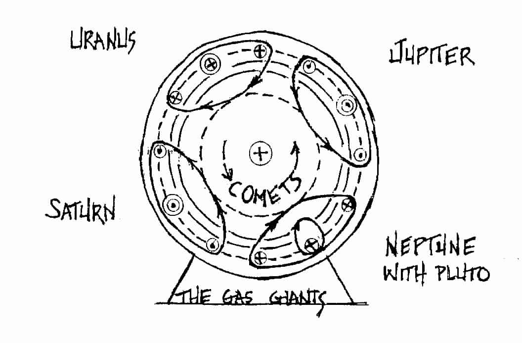
Electromagnetic Model of the Outer Planets
Here one pole is associated with each of the gas giants, forming rings or a "Great Red Spot" (Jupiter) or "Great Dark Spot" (Uranus) as the case may be. Pluto is show associated with Neptune because Pluto passes inside Neptune's orbit at times. This is not to imply that Pluto is part of the gas giant model, but to suggest how the next fractal level is associated with the outer planet level. Perhaps at Pluto the system behaves only like a simple two pole apparatus, the invariant vs. symmetric planes only, being too weak to force any more complex motion; thereafter dissipating and leaving only the symmetric plane, until approaching another star system.
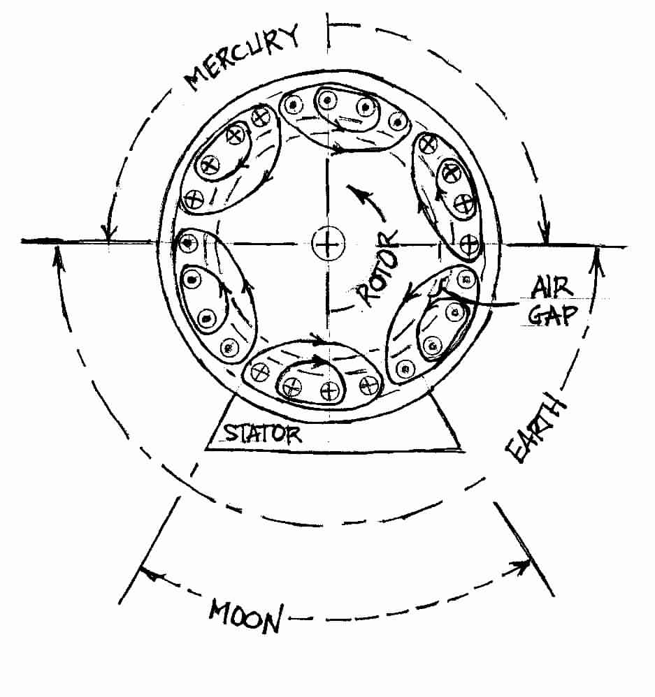
It has already been noted that a halo orbit in a rotating coordinate system about a Lagrange Point is the same as each planet's motion versus the symmetric plane. Thus, the transformation of coordinates to the symmetric plane establishes a specific Lagrange Point for each planet. ( 2 ) In this way, the loop acts as an attractor ( 14 ). The following illustration shows the rotating flux in the frequency domain for a three phase electrical system.
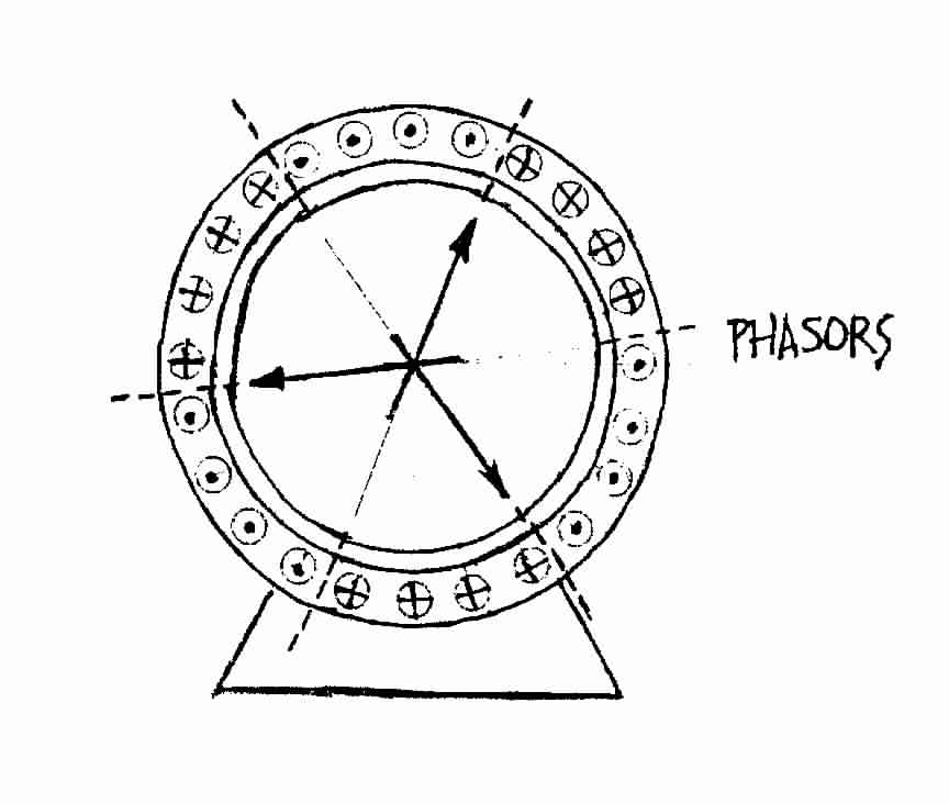
The Three Phase System
It may be convenient, in applying some of these abstract notions to the study of electrical motors and generators, that the Three Body Problem is shown by analogy as a Three Phase electrical system. Perhaps this will help to reduce the harmful harmonics created by rotating electrical devices and make them more efficient.